

| Item | Standard | Test Method |
|---|---|---|
| Resistance Value | ± 1 % | JIS C 5202, 5.1 |
| Resistance Temp. Characteristics (ppm/°C) |
* MAX TC 10 Ω and below ± 200 ppm / °C above 10Ω ± 50 ppm / ° C |
JIS C 5202, 5.2 100 ° C + Room |
| Load Life In Humidity ( Damp Heat ) | Temp. 40±2°C, 90~95% RH *R MAX ± (5%+0.05Ω) 1.5 hrs ON / 0.5 hr. OFF (1000hrs ) |
JIS C5202 7.9 |
| Load Life In Temperature (Endurance) | Temp. 70 °C * R MAX ± (5%+0.05Ω) 1.5 hrs ON / 0.5 hr. OFF (1000hrs ) |
JIS C5202 7.10 |
| Short Time Overload | ± (0.5 % + 0.05 Ω ) | JIS C 5202, 5.5 root( PR * 2.5 (5 sec.) ) |
| Solder Heat Resistance | ± (0.5 % + 0.05 Ω ) | JIS C 5202, 6.4 350 °C ± 10 °C 3 sec |
| Temp. Cycling Resistance | ± (0.5 % + 0.05 Ω ) ( 5 cycles ) |
JIS C 5202, 7.4 -55 °C / +155 °C |
| Dielectric Withstanding Voltage | ± (0.5 % +0.05 Ω) V – Block 60 sec. |
JIS C 5202, 5.7 |
| Solder ability | Covered with new solder by 95 % (240°C for 5 sec.) | JIS C 5202, 6.5 |
| INSULATION | 10000 MW or more V – Block , 60 sec. |
JIS C5202, 5.6 |
| Vibration Resistance | ± (0.5 % +0.05 W) Low frequency vibration 2 hrs. In each of 3 direction | JIS C-5202, 6.3 Type -A |
| HEAT RESISTANCE | ± ( 3% + 0.05 W ) | 1000 hrs in the thermostatic bath At 155°C |
| COLD RESISTANCE | ± ( 3% + 0.05 W ) | 1000 hrs in low temperature bath At -55°C |
| MOISTURE RESISTANCE (Damp Heat) | ± ( 3% + 0.05 W ) | 1000 hrs in 90 ~95% thermo- Humidistat bath at40°C without load |
| Drop Test | Drop the resistor from 1 Meter height to a wooden board ( 3 cm thick )
for lead wire bending ) |
|
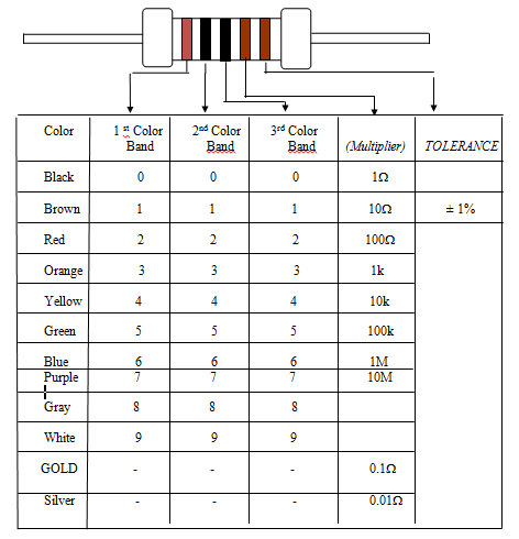
The nominal resistance value and allowable tolerance of resistance shall be indicated by
colors. The indication method is shown in Table 4.
Table 4 : Color Band Indication (± 1%)
